PCjs Machines
Home of the original IBM PC emulator for browsers.
PCjs Blog
Mysteries of the IBM Serial Adapter
While I was working on some code to Control Machines By Serial Port, I ran into a few problems that people were probably first running into over 36 years ago.
For example, there’s the fact that the INT 14h “Communication Services” services in IBM’s ROM BIOS were rather lame. Instead of using interrupt-driven I/O, which IBM’s first 8250-based Asynchronous Communications Adapter was perfectly capable of supporting, their INT 14h Send and Receive functions used polled I/O instead.
And the polling logic is rather strange. Here’s what their Send function does:
- Turn on DTR (Data Terminal Ready) and RTS (Request To Send)
- Wait for DSR (Data Set Ready), in a 64K loop
- Only after DSR is set, wait for CTS (Clear To Send), in a 64K loop
- Only after CTS is set, wait for THRE (Transmitter Holding Register Empty), in a 64K loop
- Only after THRE is set, write the data to send
What’s wrong with this logic? First, RTS is not normally used when sending data; it’s used to request data. It’s like a very gracious RSVP, requesting the pleasure of the other party’s data, at their convenience. Unfortunately, this function is 100% focused on sending and 0% focused on receiving, so telling the other end that we can receive data now is really an invitation to lose data.
Second, we have three back-to-back 64K loops. All three conditions could have easily been checked with a single loop. And why does each loop perform exactly 65536 iterations? It seems likely that the only relationship between the number 65536, the speed of the 8088 CPU, and real-world serial communications, is, um, nothing.
DOS 2.0 and the CTTY Command
Long before I ever wanted to control a PC with a serial port, there was PC DOS 2.00 and the CTTY command, which allowed you to redirect all DOS screen and keyboard I/O to the serial port of your choice; e.g.:
CTTY COM1
Since the ROM BIOS didn’t bother programming an initial baud rate for any of your COM ports, DOS did it for you, selecting 2400 baud. In 1981, 300 baud was fairly common when using modems, but for direct connections, 9600 baud was more typical. So why did DOS choose 2400 baud? Probably because it was relying on those lame INT 14h services that used polled I/O, and at 9600 baud, characters would probably get dropped.
As an aside, if all you wanted to do was “capture” your PC’s output, another option was the Ctrl-PrtSc key combination, which would tell DOS to echo all output to LPT1, until you pressed Ctrl-PrtSc again. For machines without a PrtSc key (or for machines that were using a COM port, courtesy of CTTY), you could also use Ctrl-P – which, in fact, is what DOS always converted Ctrl-PrtSc to internally.
Unfortunately, DOS 2.0 immediately enabled echo to LPT1 whether you had a printer or not. DOS first called the ROM’s INT 17h “Printer Status” function (02h), which simply returned 02h back to the caller if the printer didn’t exist, and 02h (by virtue of bit 7 being clear) implied that the non-existent printer was busy. And since it would remain that way forever, your machine was hung.
Another way to effectively hang your machine was:
CTTY LPT1
because, even if you did have a printer, printers have no input mechanism, so even if you wanted to undo the CTTY command with:
CTTY CON
you couldn’t. Granted, some other type of I/O device could be connected to your parallel port that did provide input, but that usually wasn’t the case.
As an aside to this aside, stay tuned for a future blog post that discusses all the special keys that DOS supported.
It’s 2018 and We Can Do Better
To make serial I/O more reliable not only for my own control applications but also for DOS and commands like CTTY, the sensible solution seemed to be: write an INT 14h TSR that replaces the ROM BIOS functions with compatible interrupt-driven functions.
And so the PCjs INT14.COM utility was born.
The initial version of INT14.COM worked well inside my own PCx86 machines, but when I ran it on my real IBM PC AT, it never received any data. It turned out that the interrupt handler wasn’t being called. I double and triple checked that I had:
- Properly set the serial adapter’s Interrupt Enable Register
- Properly unmasked the correct IRQ in the 8259’s Interrupt Mask Register
and I had. So I thought, well, maybe that adapter’s interrupt circuitry is toast, so let’s try another adapter. Same problem. Both adapters were IBM PC AT Serial/Parallel adapters that used the NS 16450 chip, so I thought, well, let’s try an original IBM PC Asynchronous Communications Adapter with an 8250 chip, in case there’s some subtle difference between them.
Still no interrupts.
At this point, it was time to find another way to verify that these old serial adapters worked. Coincidentally, friend and former co-worker Anthony had just given me an original Microsoft Serial Mouse, complete with green buttons, metal ball, and a DB-25 serial connector. It was the perfect test device for my 8250 serial adapter.
I dug up an old Microsoft Mouse 5.0 System Disk, plugged the mouse in, ran MOUSE.COM, and sure enough, the mouse was detected, the driver installed, and SYMDEB confirmed that its serial interrupt handler was receiving interrupts. WTF?
So I rooted around in some old mouse driver source code, and I came across these interesting lines:
add dx,3fch-3f8h
mov al,00001011b    ;reset RTS, reset DTR, and
                    ; enable hardware interrupt enable
out dx,al           ;this powers up the mouse
which was a bit of a head-scratcher, because bit 0 is “DTR” and bit 1 is “RTS”, but bit 3 is “OUT 2”. So I checked the original IBM PC Technical Reference Manual (which covers the older 8250-based serial adapter) and the IBM PC AT Serial/Parallel Reference Manual (which covers the newer 16450-based serial adapter), and neither manual had anything special to say about “OUT 2”.
For example, the IBM PC Technical Reference says:
Output 2 (OUT 2), Pin 31: User-designated output that can be set to an active low by programming
Bit 3 (OUT 2) of the MODEM Control Register to a high level. The OUT 2 signal is set high upon a
Master Reset operation.
...
MODEM Control Register
...
Bit 3: This bit controls the Output 2 (OUT 2) signal, which is an auxiliary user-designated output.
Bit 3 affects the OUT 2 output in a manner identical to that described above for bit 0.
And the IBM PC AT Serial/Parallel Reference Manual says:
Output 2: (-OUT 2), Pin 31-User-designated output that can be set to an active level by programming
bit 3 (-OUT 2) of the modem control register to an inactive level. The '-OUT 2' signal is set inactive
upon a master reset operation. Pin 31 controls interrupts to the system.
...
Modem Control Register
...
This bit controls-the' -Output 2' (-OUT 2) signal, which is a spare the programmer can use. Bit 3
affects the '-OUT 2' output in the same way bit 0 affects the '-DTR' output.
Yes, there is a tiny extra comment in the later manual (Pin 31 controls interrupts to the system),
but it’s in the hardware section, not the programming section. And, yes, the schematics do reveal that
“OUT 2” controls delivery of the “INTRPT” signal:
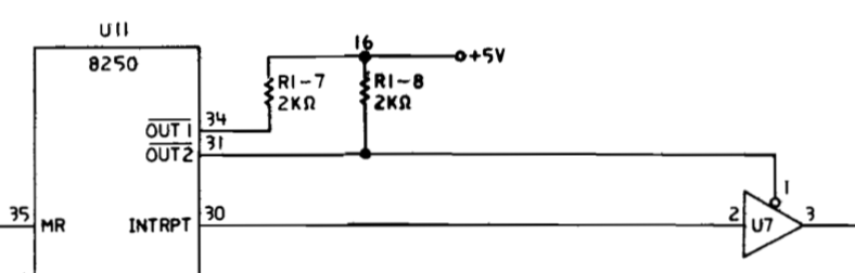
And that was supposed to be clear?
Apparently, this use of the “OUT 2” signal was an IBM innovation which was never really explained or rationalized, but third-party manufacturers zealously copied it, because even my third-party DTK serial adapter requires setting “OUT 2” to enable interrupts.
The good news is that the PCjs INT14.COM utility appears to be working well now, and I’ve since added a few related utilities, including DOWNLOAD.COM, which offers the rudimentary ability to “download” binary files onto my old IBM PC from my MacBook Pro via a USB-to-serial adapter running at a blazing 9600 baud – all thanks to this new set of interrupt-driven INT 14h services.
Jeff Parsons
Mar 16, 2018