PCjs Machines
Home of the original IBM PC emulator for browsers.
PCjs Blog
Emulating IBM PC Cursors
Since I’m finally in possession of a working IBM Monochrome Display, IBM Color Display, and IBM Enhanced Color Display, along with the requisite video cards – specifically:
- IBM Monochrome Display Adapter (MDA)
- IBM Color Graphics Adapter (CGA)
- IBM Enhanced Graphics Adapter (EGA)
I decided it was time to start digging into some of their idiosyncrasies. And there are a fair number of them. These are little quirks that emulators often don’t bother with. I started with one of the simpler features that all the video cards support: programmable cursor shapes.
Hardware Cursor
For purposes of this blog post, the term “cursor” refers to the blinking cursor that any of the above video cards display in a text mode. It’s also known as the “hardware cursor”, because the video hardware automatically draws it, erases it, and redraws it multiple times per second, all without any assistance from the processor.

(Normal Blink)
However, by writing to the appropriate video card registers, the processor does have the ability to:
- Move the cursor anywhere on (or off) the screen
- Change the shape (thickness) of the cursor
- Change the rate at which the cursor blinks (at least on some video cards)
Cursor Shapes
Depending on the text mode, character cells are generally either 8 or 14 scan lines high. The scan lines within a cell are numbered from top to bottom, with 0 being the top scan line, and 7 or 13 being the bottom. Cursors are defined as ranges of scan lines, and two CRT controller registers determine the starting and ending scan line of the cursor:
- Cursor Start: Register 10 (0x0A)
- Cursor End: Register 11 (0x0B)
Here are IBM’s default values for the Cursor Start and Cursor End registers, expressed as ranges:
- MDA: 11-12
- CGA: 6-7
- EGA: 11-13 (assuming either a Monochrome or Enhanced Color Display)
Even though it looks like the default EGA cursor would be 3 scan lines tall, it’s actually only 2, because unlike the MDA and CGA video cards, the EGA draws cursor scan lines up to but not including the scan line at Cursor End. Even IBM’s own EGA Technical Reference manual gets this detail wrong.
You might be tempted to think that this idiosyncrasy of the EGA means that if the Cursor Start and Cursor End register are equal, then no cursor at all is drawn. But no, assuming the cursor is visible, the hardware always draws at least one scan line before deciding whether to draw more.
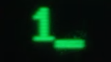
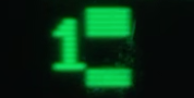
Below are screenshots of the default (11-12) MDA cursor, along with a thinner (11-11) cursor.

Cursor Visibility
There are number of ways to “hide” the cursor:
- Position the cursor to an off-screen location
- Turn the cursor’s “blink” bit off
- Set the Cursor Start register to a value greater than or equal to the number of scan lines
The cursor’s “blink” bit is bit 5 in the Cursor Start register. This means that only bits 0-4 are used to define the starting scan line, permitting any value from 0 to 31. Since, for example, 31 is larger than the number of character scan lines used on any of these cards, writing 31 to the Cursor Start register effectively disables (“hides”) the cursor on any card.
Cursor Wrap Around
Setting the Cursor End register to a value greater than or equal to the number of scan lines has a different effect: the scan line generator logic wraps around to zero and continues until it reaches the Cursor Start scan line, resulting in a block cursor equal to the full height of the character cell.
There is one unusual exception to this behavior on the EGA: if the value in the Cursor End register modulo 16 is equal to the Cursor Start register, then the cursor is drawn as if Cursor Start was equal to Cursor End, which (as described above) results in a single scan line.
For example, if you set Cursor Start to 4 and Cursor End to 20, since 20 mod 16 == 4, the cursor will be only one scan line thick – again, only on an EGA.

Cursor Wrap Around with Split
Setting the Cursor End register to a value less than the Cursor Start register also causes wrap around, but the wrap around stops when the internal scan line value reaches Cursor End, thereby leaving a gap between the ending and starting scan lines. The effect makes it appear as if the cursor has been “split” into two separate blocks, with the top block always starting at the top and the bottom block always ending at the bottom.
And once again, there is slight difference between the EGA and the older cards: setting Cursor Start to 5 and Cursor End to 4 will result in a split cursor on the EGA with a gap of exactly one scan line, whereas those same settings on older cards will result in a solid cursor, since they draw scan lines up to and including the line at Cursor End.
Order Matters
Let’s assume the default cursor is displayed:
- Cursor Start: 11
- Cursor End: 12 (or 13 on an EGA)
Now if you set Cursor Start to 14, the cursor disappears, and if you THEN set Cursor End to 15, the cursor is still gone.
If you start over and set Cursor End to 15 first, you’ll get the wrap-around block cursor, and if you THEN set Cursor Start to 14, the cursor is still a block.
So, at the end of both of those scenarios, the results are different, even though BOTH Cursor Start and Cursor End were programmed with EXACTLY the same values (14 and 15, respectively). Only the order in which they were programmed differs.
The easiest way to interpret this behavior is to assume that whenever one register is “out of bounds” (i.e., set to a value greater than or equal to the cell height), any “out of bounds” write to the other register is effectively ignored.
About That Blink Bit
I mentioned earlier that bit 5 of the Cursor Start register was a “blink” bit. That was a “bit” of an oversimplification. Here’s what the Motorola 6845 CRT Controller datasheet has to say about that register:
Cursor Start Register (R10) - This 7 bit write-only register controls the cursor format.
Bit 5 is the blink timing control. When bit 5 is low, the blink frequency is 1/16 of the
vertical field rate, and when bit 5 is high, the blink frequency is 1/32 of the vertical
field rate. Bit 6 is used to enable a blink. The cursor start scan line is set by the
lower 5 bits.
The datasheet notwithstanding, the behavior of bits 5 and 6 is really card specific. On the MDA, here is what I observed (bit 6 is the left digit, bit 5 is the right):
- 00: normal blinking (off and on periods equal)
- 01: no blinking
- 10: no blinking
- 11: slower blinking (off period longer than on period)
So, it’s not really accurate to say that bit 5 is the “blink” bit, unless you ensure that bit 6 is always clear as well.
Here’s what the slower blinking cursor looks like:

(Slower Blink)
EGA and later cards don’t use the original Motorola 6845, so their treatment of these bits is, um, a bit different.
In particular, the EGA Technical Reference Manual says simply that the “blink” bits are NOT USED, and the IBM EGA BIOS
claims that when, calling the “Set Cursor Type” function (0x01), SETTING BIT 5 OR 6 WILL CAUSE ERRATIC BLINKING OR NO
CURSOR AT ALL. That last comment may have referred to a pre-production model, because I tried setting those bits on a
genuine IBM EGA board, and I saw no effect on the cursor at all.
Experimenting With Cursors
A few PCjs machines have enabled TestMonitor Support, which allows you to use one of the machine’s serial ports (usually COM2) to control and issue commands to the machine.
Some of the video-specific TestMonitor commands include:
cursor 11 13(programs the default EGA cursor)cursor 4 19(programs a block cursor)cursor 4 20(programs a single-line cursor, for reasons explained above)
For more information, go to the TestMonitor Support page.
PC Magazine CTYPE and STICK Utilities
For more fun with cursors, take a stroll down memory lane with a few old PC Magazine utilities.
The November 10, 1987 issue of PC Magazine featured an article, “Getting Control of Your Cursor”, by Jeff Prosise that described a utility named CTYPE, which you can see running in the machine below.
The November 24, 1987 issue of PC Magazine featured a related article, “A Colorfast Screen and Stable Cursor”, also by Jeff Prosise, that described a utility called STICK, which you can find on the PCjs diskette labelled “PC Magazine (Vol. 06 No. 20)”.
[PCjs Machine "ibm5160-msdos320"]
Waiting for machine "ibm5160-msdos320" to load....
Jeff Parsons
Mar 20, 2018